


 134 / 162

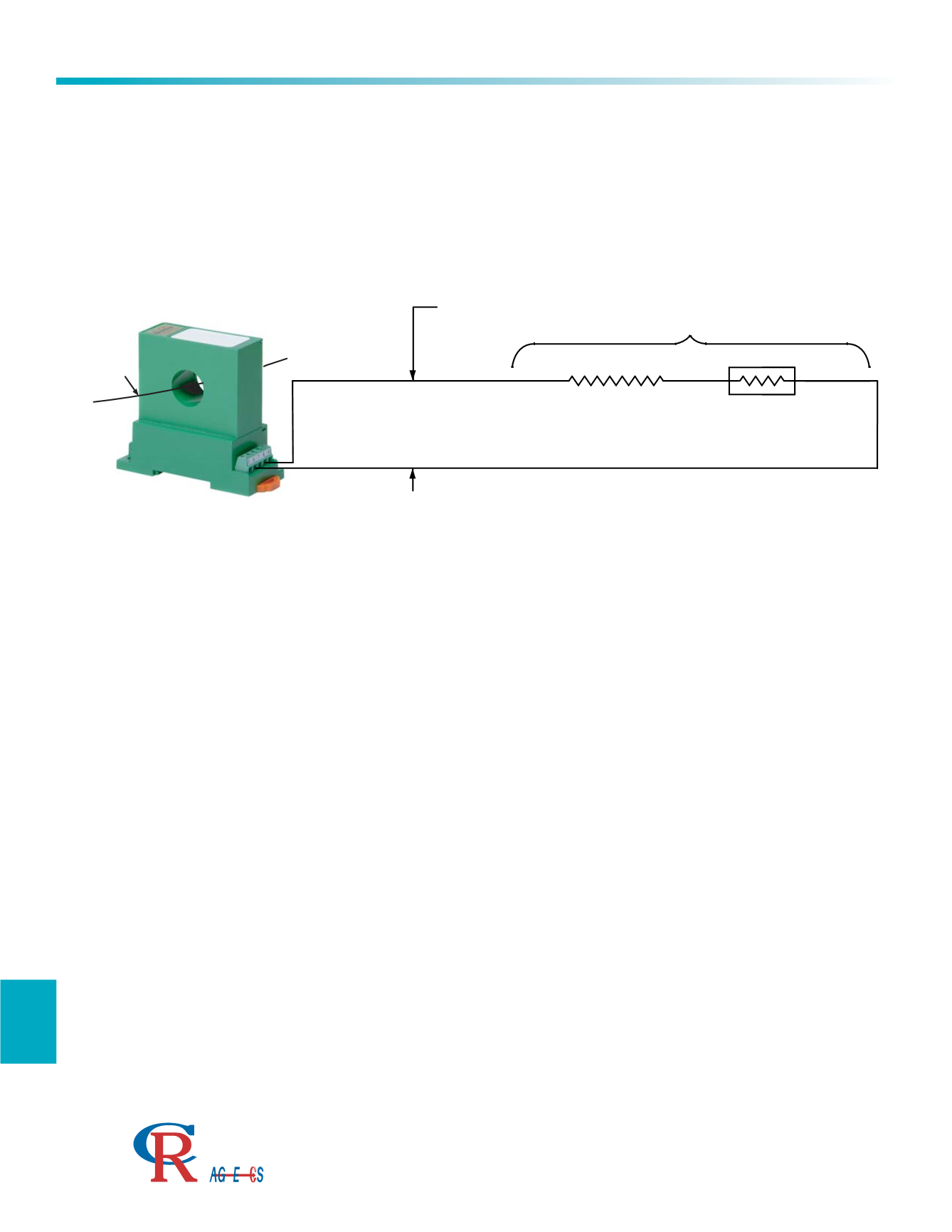
Using the Self Powered CR4210/11 Series Current Transducer
134
H
Applications
3500 Scarlet Oak Blvd. St. Louis MO USA 63122 V: 636-343-8518 F: 636-343-5119
Web:
http://www.crmagnetics.comE-mail:
sales@crmagnetics.comThe Professional
Energy Monitoring
Company
ISO 9001:2008QualityManagementSystem
M N TI
TOTAL LOAD RESISTANCE
0-10 Vdc for
CR4211
INSTRUMENTATION
RESISTANCE
INTERCONNECT
RESISTANCE
-
+
0-5 Vdc for
CR4210
I
PRIMARY
The 4210 and 4211 series transducers are self-powered variable voltage devices that automatically adjust their DC
voltage output to maintain a DC voltage that is proportional to the Average RMS Value of the AC current flowing
through the window of the transmitter. The 4210 outputs 5VDC and the 4211 outputs 10VDC for full scale AC input
current.
Verify that the correct polarity is observed as shown. The 4210/11 series are polarity protected, so damage
should not occur if connected in reverse polarity.
Insure that the total loop resistance (instrument plus wire) exceeds the minimum load resistance for the range
chosen. Most commonly, an instrument with a burden of 1 Meg ohms is chosen. If the total loop resistance
is less than required, the transducer will not function according to published specifications.
Twisted pair wire should be adequate for most applications but shielded/twisted pair wire with the shield
grounded at the instrumentation end may be required for the most severe environments. Refer to the
instrumentation installation manual for more details regarding interconnect requirements.
The output is calibrated to be proportional to the Average RMS of the current primary at 60 Hz. Signals from
devices such as SCR and variable speed drives will not produce an accurate indication of RMS current levels.
The first step in troubleshooting would be to check the voltage across all of the components in the loop.
Transducers may be mounted in close proximity to each other without concern for magnetic interaction.
An external current transformer may be attached to the transducer for applications that require monitoring
current levels above 200 AAC.