


 153 / 162

H
Calculating Ratio Errors
153
UNDERSTANDING CURRENT TRANSFORMER RATIO ERROR AND EXCITATION CURVES
An example of calculating the actual secondary current, instrumentation voltage and error percentage is as follows:
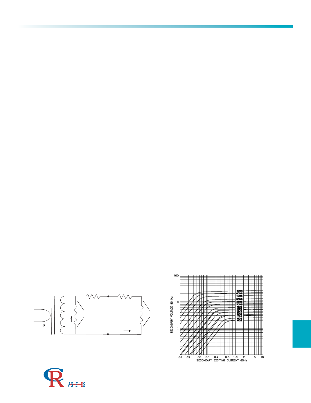
Determine the total burden terminal resistance R B across the secondary of the current transformer.This includes the secondary instrumenta-
tion resistance R I and any resistance in the interconnecting leads RL.
For: R I = 0.02 ohm & R L = 0.01 ohm R B =.02 +.01 = .03 ohm
Add the total burden resistance to the secondary winding DC resistance R S .From figure 2 for a 200:5 current ratio transformer:
R S = 0.034 ohms.03 + 0.034 = .064 ohms
Select a value of secondary current at a point you desire to determine the ratio error
For: I S = 3.75 A
Calculate the secondary voltage E S required for the current to flow through the total secondary resistance.
E S = I S x R E S = 3.75 x 0.064 = .24 V
Find the secondary voltage E S on the vertical scale of the excitation curve and read over to the 200 line and down to the horizontal scale
for the secondary exciting current I E .
I E = .013 A
The primary current will be the turns ratio times the sum of the exciting current and the secondary current
I P = N S / N P x (I E + I S ). I P = 40 x (.013 + 3.75) = 150.52 A7.
The voltage developed across the instrumentation resistor will be the secondary current times the instrumentation resistor
E I = I S x R I .E I =3.75 x .02 = 0.075 V
To calculate the percentage ratio error,divide the exciting current by the secondary current times 100.
I E / I S x 100..013 / 3.75 x 100 = 0.35 %
H2
H1
N
P
I
P
I
E
I
S
X1
X2
N
S
R
S
R
L
R
1
E
1
E
S
N
P X
I
P =
N
S
(
I
E
+
I
S
)
CURRENT TRANSFORMER RATIO ERROR AND EXCITATION CURVES
Applications
3500 Scarlet Oak Blvd. St. Louis MO USA 63122 V: 636-343-8518 F: 636-343-5119
Web:
http://www.crmagnetics.comE-mail:
sales@crmagnetics.comThe Professional
Energy Monitoring
Company
ISO 9001:2008QualityManagementSystem
M N TI