


 133 / 162

Developing Voltage From 4-20mA Current Loops
133
3500 Scarlet Oak Blvd. St. Louis MO USA 63122 V: 636-343-8518 F: 636-343-5119
Web:
http://www.crmagnetics.comE-mail:
sales@crmagnetics.comThe Professional
Energy Monitoring
Company
ISO 9001:2008QualityManagementSystem
M N TI
Applications
H
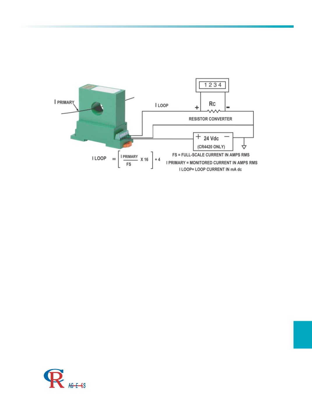
Many of the Analog Transducers from CR Magnetics provide a 4 to 20mA current loop to communicate sensed values.
These loops can be converted to a voltage for input to a wide variety of instrumentation devices including panel
meters, data acquisition systems, and programmable controllers. By adding a precision resistor in series with the
loop, a voltage is developed, which can then be inputted to the instrumentation. In the diagram below, a current
transducer is used to show this concept.
The tolerance of the resistor is critical. Tolerances of the system are additive – using a 0.5% percent transducer in
conjunction with a 1% resistor results in a 1.5% tolerance system.
The temperature coefficient of the resistor is a key factor. All electronic devices exhibit some variance with
temperature. If the resistor has a large variance with temperature, the accuracy of the system will also vary with
temperature. Self-heating of the resistor must also be considered. A typical design of 5VDC at full scale (20mA)
requires a nominal resistance of 250 Ohms (5/.020). The power generated in this resistor at full scale is Volts
times Amps or 5 X .020 = .100 Watts. Choosing a 1/8 Watt (.125) resistor will provide reasonable safety against
destruction, but will cause a significant temperature rise in the resistor. This rise in temperature can result in
significant changes in the value of the resistance. For instrumentation, a resistor with a power rating of at least
10 times the expected full scale power is recommended.
The resistor should be mounted as close as possible to the instrumentation. Once the signal is converted from
current to voltage, voltage drops from wire resistance introduces errors in the signal.
Whenever possible, use similar materials for all wire connections. Galvanic reactions from dissimilar metals can
introduce errors in the readings. An extremely low galvanic reaction such as 5mV introduces a .1% error at 5VDC
full scale. Smaller reading levels results in this error being more significant.