


 14 / 162

14
Data Stream
B
3500 Scarlet Oak Blvd. St. Louis MO USA 63122 V: 636-343-8518 F: 636-343-5119
Web:
http://www.crmagnetics.comE-mail:
sales@crmagnetics.comThe Professional
Energy Monitoring
Company
ISO 9001:2008QualityManagementSystem
M N TI
RS485 Digital Transducer
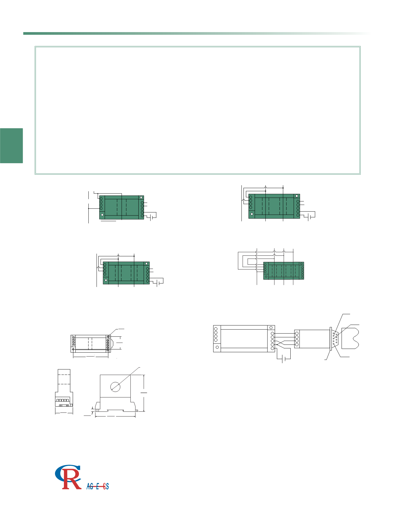
CRD5110
Single Element, 2-Wire
LOAD
1
2
3
4
5
6
7
9
8
L N
LINE
-
-
+
+
SUPPLY
485
LOAD
8
7
9
5
6
1
4
2
3
L2
L1
N
LINE
-
-
+
+
SUPPLY
485
N
L3
L1 L2
1
3
4
2
LOAD
9
8
7
6
5
LOAD
8
7
9
5
6
1
4
2
3
L3
L1
L2
LINE
-
-
+
+
SUPPLY
485
CRD5150
Dual Element, 3-Wire
CRD5150
Dual Element, 3-Wire
CRD5170
3 Element, 4-Wire
ASCII Simplified Programming Commands
A simplified data structure is used with only 6 commands required for full control of
the transducer. Commands are : Read Transducer Name, Read Configuration, Set
Configuration, Read Measurements, Read Energy Totalizer and Clear Energy
Totalizer. For illustration, the following commands are used to read data from a
CRD5170 3 Phase, 4 Wire Transducer with a device address of 00.
Command Transducer to Read Data:
#00A<cr>
Transducers Response:
>+[% FS Voltage L1-N ]+[% FS Current L1 ]+[% FS
Voltage L2-N ]+[% FS Current L2 ]+[% FS Voltage L3-N ]+[% FS Current L3 ,][+/- % FS
Power][+/-% FS VARS][+/-Power Factor][Frequency]<cr>
Command Transducer to Read Energy Totalizer:
#00W<cr>
Transducer Responds:
01[+/-KWHr]{\[+/-KVHr][check sum]<cr>
Note: This is for illustration purposes only, See Applications Guides (Section I
for complete instructions.
SPECIFICATIONS
Connection Diagram
L1
L2
LINE
LOAD
LINE
LOAD
N L1 L2 L3
N 1
LINE
LOAD
LINE
L2
L1
L3
LOAD
SUPPLY
485
DATA+
DATA-
GND
+5VDC
COM
RS232
CRD485-232
SUPPLY
5
6
7
9
8
+ -
DATA STREAM
TRANSDUCER
TX
RX
GND
DB 9, FEMALE
1
2
3
4
CRD485-232
RS485 to RS232 Converter Accessory
Connect PC to RS485 Bus
Basic Accuracy: .......................0.5%
Calibration: ..............................True RMS Sensing
Thermal Drift: ..........................500 PPM/°C
Operating Temperature
1
: ..........0°C to +60°C
Installation Category: ..............CAT II
Vibration Tested To: .................IEC 60068-2-6,1995
Pollution Degree: ....................2
Insulation Voltage: ..................2500 VDC
Altitude: ..................................2000 meter max
Frequency Range: .................20 Hz - 5 KHz
MTBF: ....................................Greater than 100K hours
Cleaning: ................................Water-dampened cloth
Supply Voltage
2
: ......................24 VDC ±10%
1) RH 5% to 95%, non-condensing 2) 0.4% max. ripple Vpp
3) Factory default settings: address 01, baud rate 9600, no parity,
Torque Specifications: ....................3.0 inch lbs (0.4Nm)
Response Time: .......................250 ms. max. 0-90% FS
Relative Humidity: ...............80% for temperatures up to
31°C and decreasing linearly to 50% at 40°C
Output Resolution: ..................................................16 bit
Transducer fanout on common bus: ...................64 max.
Baud Rate
3
: ...............
1200, 2400, 4800, 9600,19.2K
.bps
A/D Conversion Type: ..................4th order Delta Sigma
Device Address
3
: ............................................00 to FF
Data Format: .... .....................................................ASCII
Supply Current:..................Typical 30mA Max 30mA
Weight:.. ..............................................................0.5 lbs.
no flow control, 1 stop bit
2.874
(73)
0.79
(20)
2.99
(76)
0.20
(5.1)
(83)
3.268
OUTLINE DRAWING
9
8
7
6
5
1
2
3
4
1.42
(36)
DIA.
0.14
(3.5)
1.06
(26.8)
2.874
(73)
0.26 (6.5) Dia.
1 hole for single element
2 holes for two element
3 holes for three element