Understanding Current Transformer Ratio Error and Excitation Curves
A current transformer follows all the standard physical laws for electrical transformers. The primary winding is usually a very low impedance and therefore treated as a "brute force" constant current source. Faraday's law of ampere-turn balance states that the number of turns in the primary winding times the primary current must equal the number of turns in the secondary winding times the secondary current. Therefore, since the primary is a constant current source, the secondary becomes a constant current source proportional only to the turns ratio.
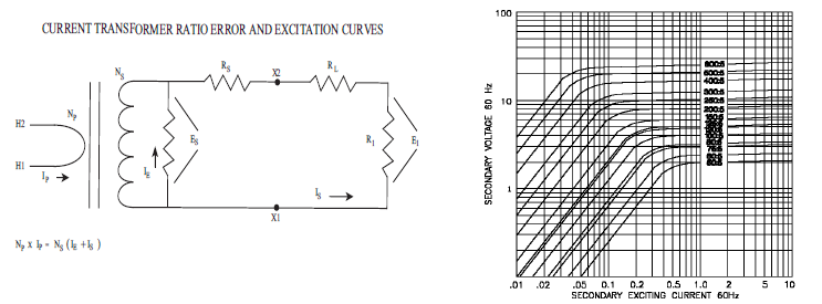
Other factors come in to play that affect the basic Faraday's relationship, such as the non-linear properties of the core material, eddy current, hysteresis and IR losses. As Figure 1 illustrates, the eddy current and hysteresis losses act to shunt current across the transformer secondary and are defined as excitation losses IE. Since the excitation losses are non-linear, they are determined from an Excitation Curve provided by the transformer's manufacturer. The IR losses act as a resistance RS in series with the secondary winding.
As Figure 2 illustrates, the secondary voltage Es is found on the vertical axis and the secondary exciting current IE can be found on the horizontal axis. This exciting current can best be described as the current that contributes to the current transformation ratio error.
Power transformers use the terms "Load" and "Regulation" to describe their operation. Current transformers use the terms "Burden" and "Accuracy" respectively to describe similar functions. Burden defines the connection made to the secondary winding to differentiate it from the primary connection that is generally described as the Load. Current transformers use the term Accuracy to describe what would generally be considered Regulation with a power transformer. It is important to remember that Burden and Accuracy are interdependent; generally the lower the Burden resistance, the better the Accuracy.
Designs that have the current transformer separate from the instrumentation resistor RI need to consider transformer ratio error. An example would be an ampere meter that uses an external current transformer. The transformer must have an accurately-defined current ratio to allow for interchangeability with other transformers of the same rating.
Designs that have the current transformer as an integral part of the instrumentation can place less emphasis on ratio error and consider more on the transformer's linearity. An example would be a printed circuit-board-mounted current transformer that inputs into an operational amplifier circuit. Ratio error can generally be minimized during calibration with adjustment to the offset and gain controls. The major concern to the overall accuracy of the design would then be linearity of the transformer through out the operating range.
In practice, the designer must consider various factors in selecting a current transformer: since the secondary is operating as a constant current source, a Burden resistor of lower value will provide improved accuracy but decrease instrumentation voltage (V=IR). As the instrumentation voltage is increased with a high Burden resistor, the power dissipated may become a factor (P = I2 R). Generally the designer determines the lowest voltage the electronics can handle considering such parameters as circuit noise and gains. Then the value of the burden resistor can be determined, knowing the characteristics of the current transformer and overall design requirements.
An example of calculating the actual secondary current, instrumentation voltage and error percentage is as follows:
Determine the total burden terminal resistance RB across the secondary of the current transformer.This includes the secondary instrumentation
resistance RI and any resistance in the interconnecting leads RL.
For: RI = 0.02 ohm & RL = 0.01 ohm RB =.02 +.01 = .03 ohm
Add the total burden resistance to the secondary winding DC resistance RS.From figure 2 for a 200:5 current ratio transformer:
RS = 0.034 ohms.03 + 0.034 = .064 ohms
Select a value of secondary current at a point you desire to determine the ratio error
For: IS = 3.75 A
Calculate the secondary voltage ES required for the current to flow through the total secondary resistance.
ES = IS x R ES = 3.75 x 0.064 = .24 V
Find the secondary voltage ES on the vertical scale of the excitation curve and read over to the 200 line and down to the horizontal scale
for the secondary exciting current IE.
IE = .013 A
The primary current will be the turns ratio times the sum of the exciting current and the secondary current
IP = NS / NP x (IE + IS). IP = 40 x (.013 + 3.75) = 150.52 A7.
The voltage developed across the instrumentation resistor will be the secondary current times the instrumentation resistor
EI = IS x RI.EI =3.75 x .02 = 0.075 V
To calculate the percentage ratio error,divide the exciting current by the secondary current times 100.
IE / IS x 100..013 / 3.75 x 100 = 0.35 %