


 142 / 162

The CR45 as an Open Heater/Open Winding Indicator
142
H
WIRE M
AX. WIRE
PASSES
DIAMETER
RED GREEN
1
2.00
2.50
0.29
2
1.00
1.25
0.14
3
0.66
0.83
0.13
4
0.50
0.62
0.12
N
2 / N 2.5 / N
TURN-ON
POINT
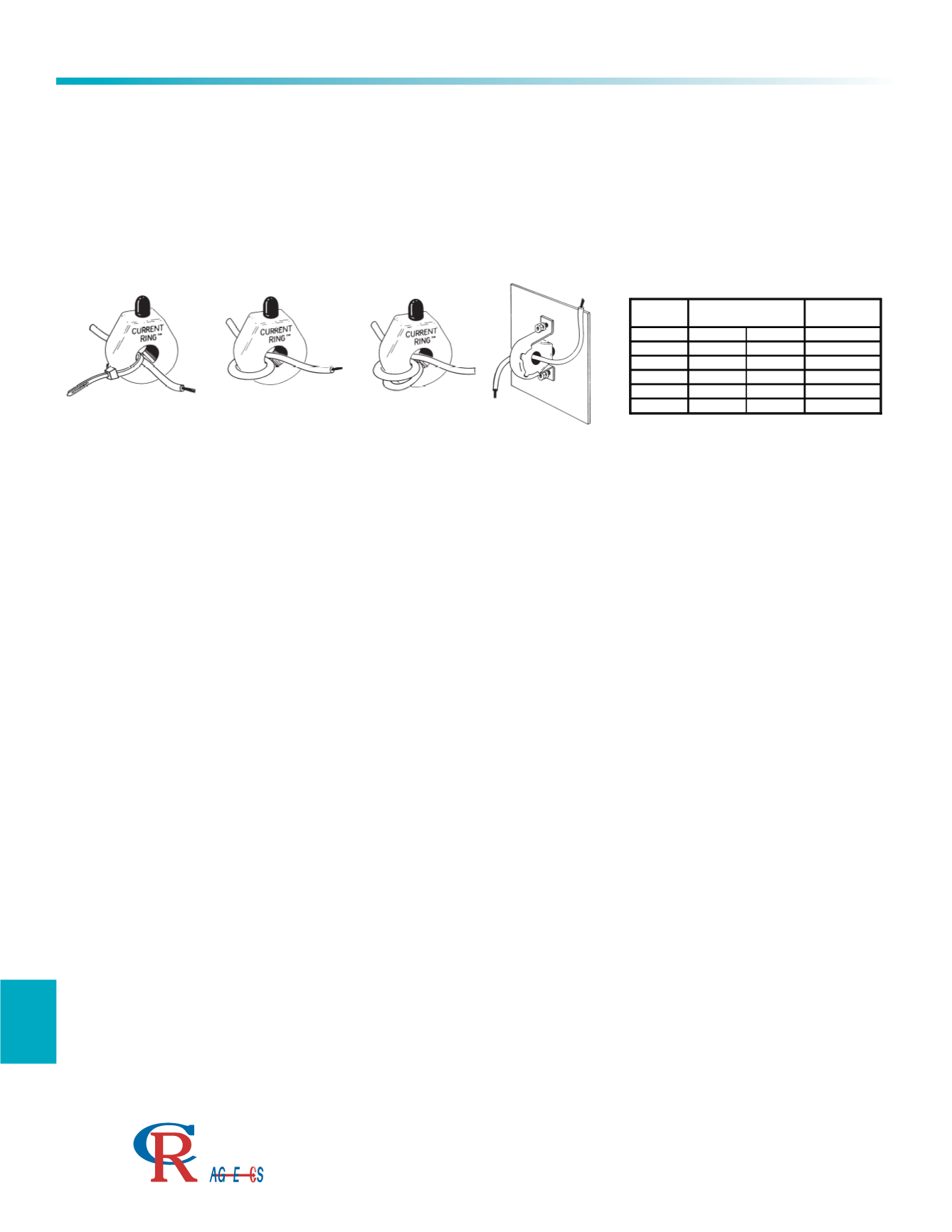
The most popular application of the CR45 indicator is to provide a method of non-intrusive troubleshooting and sta-
tus indication of heater elements and motor windings. The typical failure mode of heaters and some motors are
open circuit. When current flows, the LED is on. When the circuit is open, the LED is not on. This gives an easy
method of monitoring the status of the equipment.
The on level of the CR45 can be adjusted by increasing the number of primary turns. The table above gives the
size wire and the number of turns that can be used. Dividing the normal one turn on level of 2 amps by the
number of primary turns will give the adjusted turn on level.
The CR45 is designed to be wire mounted using the wire tie provided. For panel mounting, the MB45 is
available, along with a rubber grommet for sealing.
The maximum current that the unit can handle is 100 Amps for a single turn. Using multiple primary turns
decreases the maximum allowed by the same rules for adjusting the turn on point.
For applications where the primary current cannot be routed to an easily viewed spot to use the CR45, please
refer to our Remote Indicator line. These separate the LED and the ring sensor to give greater flexibility.
Care must be taken when using the CR45 within heater environments. The maximum operating temperature of
the unit is 70 degrees C.
Applications
3500 Scarlet Oak Blvd. St. Louis MO USA 63122 V: 636-343-8518 F: 636-343-5119
Web:
http://www.crmagnetics.comE-mail:
sales@crmagnetics.comThe Professional
Energy Monitoring
Company
ISO 9001:2008QualityManagementSystem
M N TI