


 81 / 162

Displays and Indicators
E
81
3500 Scarlet Oak Blvd. St. Louis MO USA 63122 V: 636-343-8518 F: 636-343-5119
Web:
http://www.crmagnetics.comE-mail:
sales@crmagnetics.comThe Professional
Energy Monitoring
Company
ISO 9001:2008QualityManagementSystem
M N TI
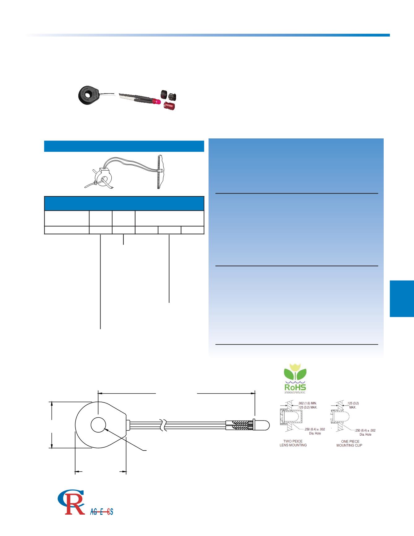
Remote Current Indicator with preset turn-on point
The
CR2530 Series
Remote Electrical Current Indicators are
an economical method for providing a visual indication of
current flow. The indicators are factory calibrated to provide
a preset turn-on point. The value of the turn-on point is deter-
mined by the customer and specified in the part number.
Attached to the transformer is a high efficiency, bi-polar LED
that illimuminates when the current is above the turn-on
point. The CR2530 standard lead length is 14 inches but can
be customized to the customer’s needs. Available LED bulb
colors are Red, Green, Blue, White, Yellow and Amber.
CR2530 Series
Applications
Monitor Status of Heater Elements
Observe Remote Loads
Indicate Phase Loss
Monitor Motor Operation
Features
Self Powered
Preset Turn-on Point
Fully Isolated
Easy to install
Panel Mounting Bracket available for Current
Transformer
Specifications
Max Current:
100 AAC Max, 600 VAC Max Rating
Frequency
50 - 400 Hz Bandwidth
Operating Temperature
-30
0
C to +60
0
C
Storage Temperature
-55
0
C to +85
0
C
Optional Mounting Bracket Non-Magnetic Aluminum
Material
Weight 0.07 LBS.
Regulatory Agencies
Bore Hole Size = 5/16”
Typical Installation
Standard Turn-on Points:
2.0, 5.0, 10, 20, 25, & 30 AAC
Custom ranges are available
Standard Lead Length is 14”
Custom ranges available
R - Red
G - Green
B - Blue
W - White
Y - Yellow
A - Amber
14.0 (355.6)
0.29 (7.4)
1.04 (26.4)
0.95 (24)
PART NUMBERS
Part Number
Turn-On
Point
LED
Color
Lead Length
CR2530