


 91 / 162

91
Current Transformers
F
Wire Lead Current Transformers
Model 17, 18, 19 Series
Applications
Remote monitoring of electrical loads
Input to electrical control system
Detect open heater elements
Indicate phase loss
Monitor motor operation
Features
Low cost
Non-contact, isolated current measurement
Surface mounting bracket available for Models 17 and 18
Two case sizes, three different standard ratios
Specifications
Frequency: 50-60 Hz
Case Material: Black thermoplastic
Maximum Continuous Primary Current 4 X Ir
Insulation Voltage 3500 Vac/1min
Regulatory Agencies
CR Magnetics offers a versatile line of rugged wire
lead current transformers. Installed around a
current-carrying wire, the sensor provides a current
output relative to the AC input current (within
specification limits). With the output connected across
a resistive load (burden), the voltage
developed is proportional to the input current.
ORDER INFORMATION
Part Number
Description
Model 17-2000
Current Transformer with wire leads,
.55 dia. opening, 2000 turns
Model 17-1000
Current Transformer with wire leads,
.55 dia. opening, 1000 turns
Model 18-600
Current Transformer with wire leads,
.55 dia. opening, 600 turns
MB-18
Surface Mounting Bracket
for Model 17 or Model 18
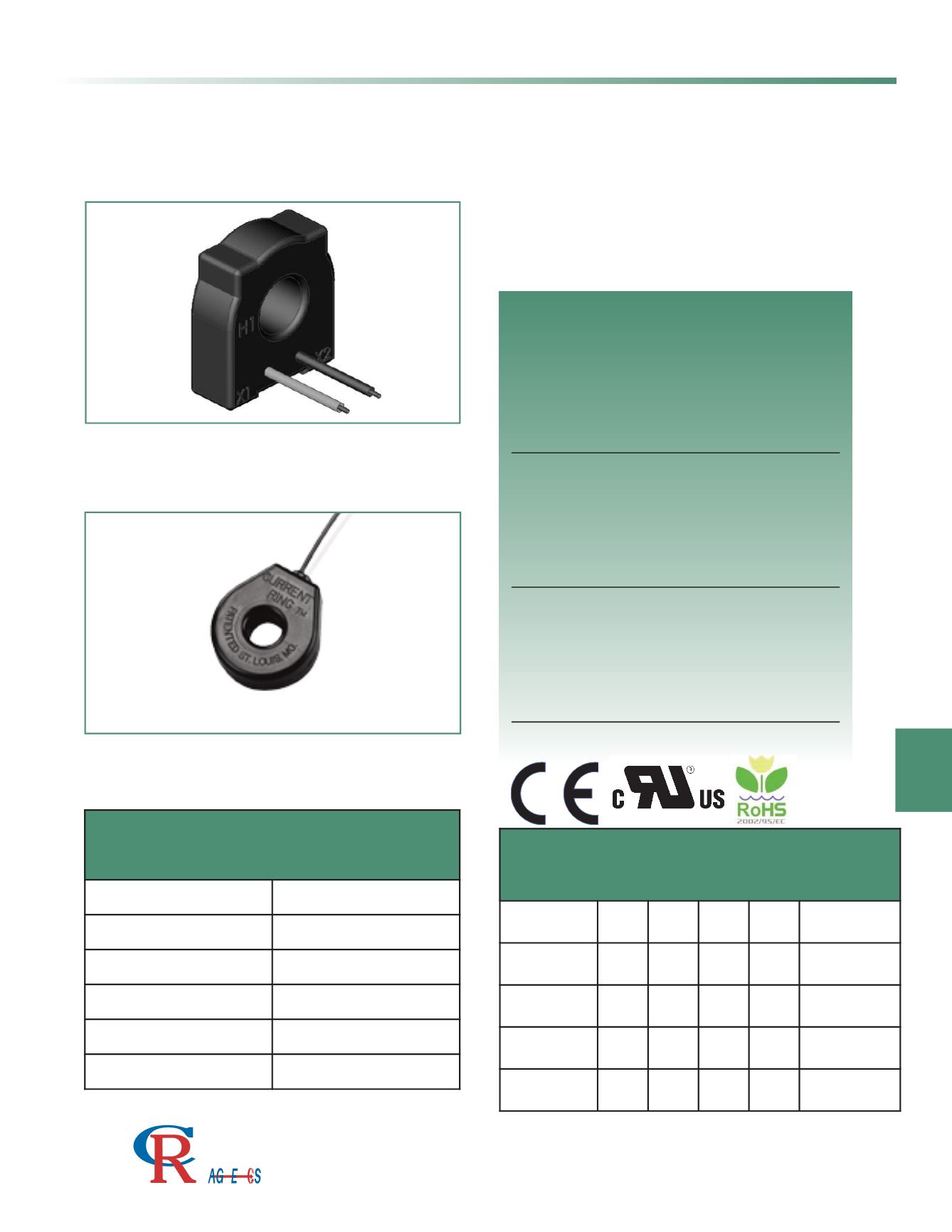
Model 19
Current Transformer with .29 dia.
opening, 230 turns
Model 19
Model 17 & 18
Shown with optional mounting bracket MB-18
3500 Scarlet Oak Blvd. St. Louis MO USA 63122 V: 636-343-8518 F: 636-343-5119
Web:
http://www.crmagnetics.comE-mail:
sales@crmagnetics.comThe Professional
Energy Monitoring
Company
ISO 9001:2008QualityManagementSystem
M N TI
BASIC SPECIFICATIONS
Part Number
Imax Vmax Te (typ.) DCR
Ω
Frequency
Model 17-2000 200
10 2010 120
50 - 2KHz
Model 17-1000 200
7.5 1010 31
50 - 2KHz
Model 18-600
100
5
605
23
50 - 2KHz
Model 19
25
2
235
3
50 - 2KHz