


 147 / 162

Applications
H
Low Cost Fan Control with Hysteresis
147
3500 Scarlet Oak Blvd. St. Louis MO USA 63122 V: 636-343-8518 F: 636-343-5119
Web:
http://www.crmagnetics.comE-mail:
sales@crmagnetics.comThe Professional
Energy Monitoring
Company
ISO 9001:2008QualityManagementSystem
M N TI
Compressor Current
Model 19
D1
C1
R3
NPN
R4
FAN
FAN
RELAY-DPDT
VDC
R2
R1
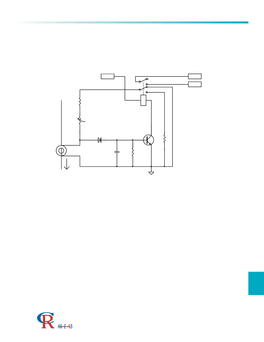
This application can be used to control many different devices. In this example, a compressor current is sensed, and
when it reaches a selected set point, the circuit turns on a relay, which controls a fan motor. The circuit is generated
with a minimum number of parts, and includes hysteresis.
The CT secondary current is applied to the resistors R1 and R2, which generates an AC voltage that is half
wave rectified by D1, and then turns on the NPN transistor. The transistor then turns on the DPDT relay, which
energizes the fan motor with one pole of the relay. The other pole of the relay is used to insert R4 into the
series R1 and R2 resistance. This immediately raises the voltage at the anode of D1, thus creating the
necessary hysteresis.
C1 provides energy storage to keep the transistor in the on state during half wave inputs. R3 discharges C1 to
aid in turn off.
The transistor should be selected keeping in mind the current gain factor, Hfe, and the turn on voltage, Vbe.
This should be weighed against the amount of secondary current received from the Model 19. Typically, a
Darlington transistor is chosen for the appropriate gain.
This design can also be applied using a bilateral silicon switch, instead of the relay shown. The transistor
activation can be used to turn on two bilateral switches, one to control a motor, and the other to provide the
hysteresis.