


 58 / 162

58
Transducers
C
3500 Scarlet Oak Blvd. St. Louis MO USA 63122 V: 636-343-8518 F: 636-343-5119
Web:
http://www.crmagnetics.comE-mail:
sales@crmagnetics.comThe Professional
Energy Monitoring
Company
ISO 9001:2008QualityManagementSystem
M N TI
Frequency Transducer
NOTE: The building installation must have a switch or circuit-breaker that is in close proximity and within easy reach of the operator. The switch or circuit breaker
shall be marked as the disconnecting device for the equipment.
SPECIFICATIONS
Basic Accuracy:......................... 0.5%
Linearity:.................................... 10% to 100% FS
Thermal Drift:............................ 500 PPM/°C
Operating Temperature:............ 0°C to +60°C
Installation Category:................. CAT II
Vibration Tested To:................... IEC 60068-2-6,1995
Pollution Degree:........................2
Response Time: ....................... 250 ms max. 0-90% FS
Supply Voltage:......................... 12 to 24 VDC
MTBF:.......................................Greater than 100 K hours
Frequency Range:....................50 Hz - 400 Hz, sine wave
Insulation Voltage:.................... 2500 VDC
Altitude:................................... 2000 meter max.
Output Load:................ 4-20 mADC -0 to 300
Ω
0-5 VDC - 2K
Ω
or Greater
Cleaning:.................... Water-dampened cloth
Relative Humidity:......... 80% for temperatures up to
31°C and decreasing linearly
to 50% at 40°C
Input Voltage:................ 20 to 250 V Peak,
(other voltage ranges available)
Supply Current:
CR6610:....................... Typical 30mA Max 40mA
CR6620:....................... Typical 50mA Max 95mA
Torque Specs.:............. 3.0 inch lbs. (0.4Nm)
Weight:......................... 0.5 lbs.
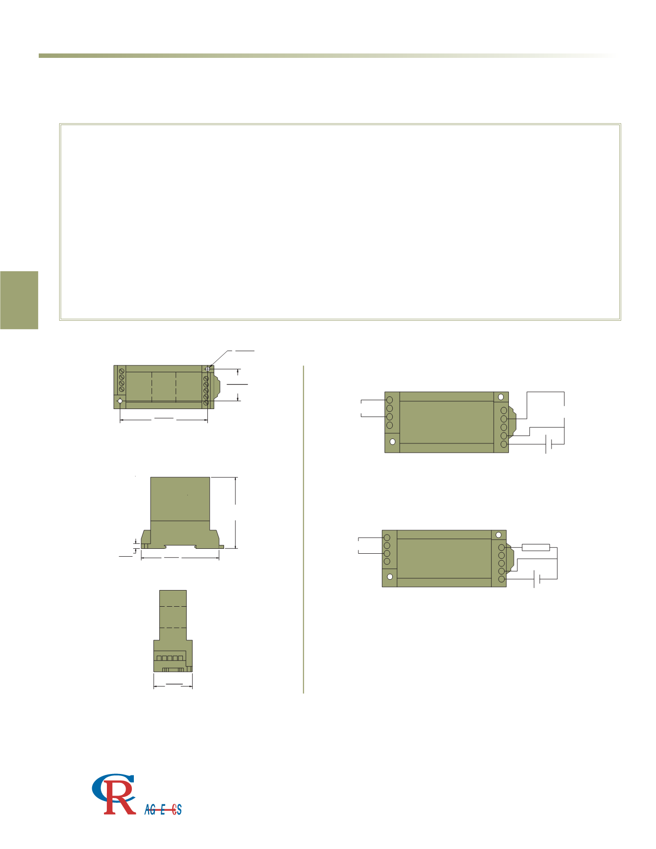
DIN RAIL / PANEL MOUNT
OUTPUT
SUPPLY
INPUT 1
+ -
+
-
1
2
3
4
5
6
7
8
9
1
2
3
4
5
6
7
8
9
INPUT 1
OUTPUT 1
+ -
SUPPLY
CR6620
4 - 20 mADC Output
CR6621
4 - 20 mADC Output
CR6622
4 - 20 mADC Output
CR6610
0 - 5 VDC Output
CR6611
0 - 5 VDC Output
CR6612
0 - 5 VDC Output
CONNECTION DIAGRAM
OUTLINE DRAWING
2.99 (76)
0.20
(5.1)
(83)
3.268
for CR4640
2.20 (56)
for CR4620
Dimensions for All CR6600 Series (shown)
3.5)
1.22
(31)
1.42
(36)
0.14
(3.5)
1.06
(26.8)
2.874
(73)
0.79
(20)
5
6
7
8
9
1
2
3
4
1.42
(36)