


 61 / 162

D
61
TYPICAL RELAY APPLICATIONS
CR
CR
M
3
5
10
15
30
25
20
"A"
"B"
3
5
10
15
30
25
20
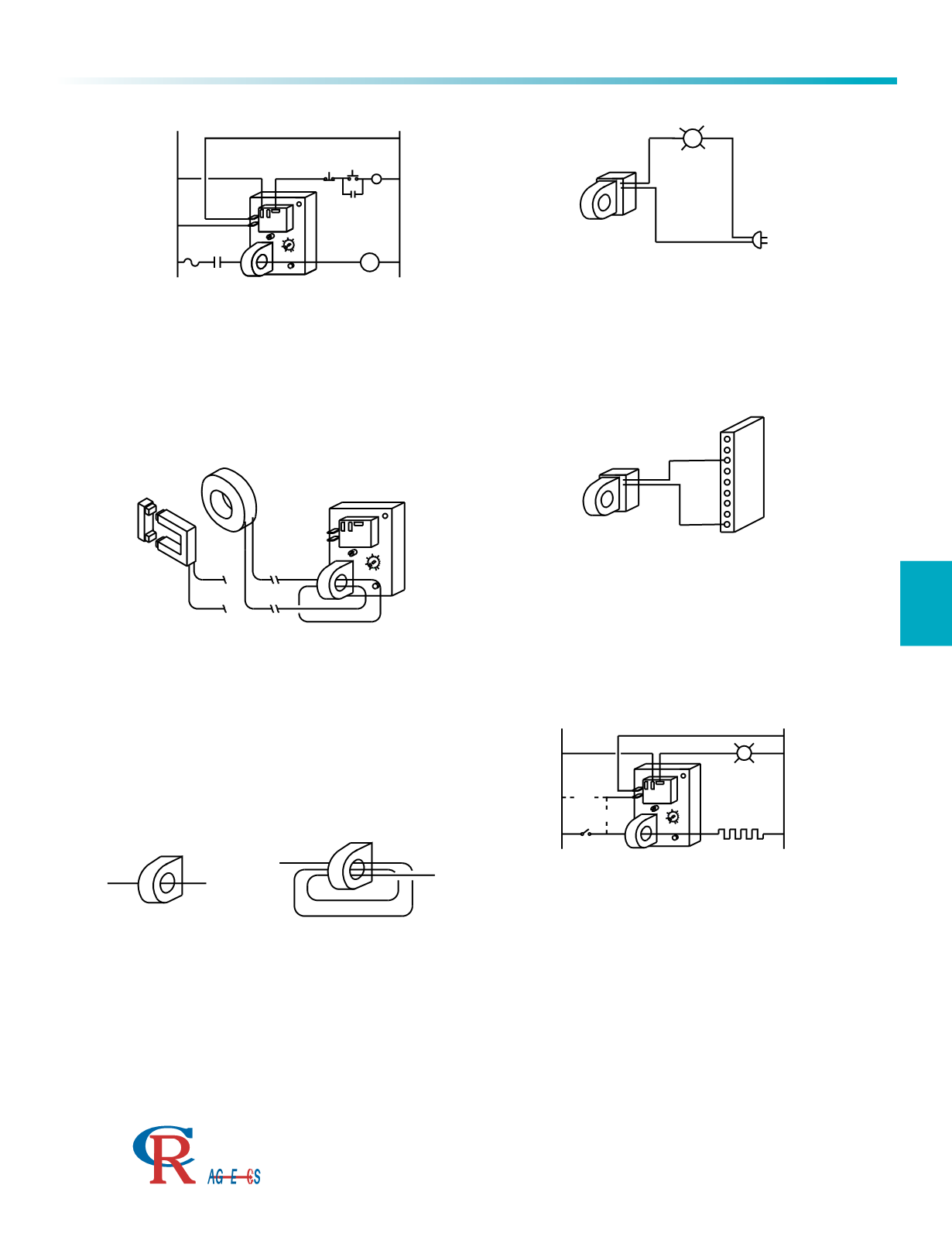
OPEN HEATER / LAMP DETECTOR
The relay may be used to provide an alarm signal to indicate an open
heater element. The current-carrying wire is routed through the window
opening. With the"EL" (Energized on Low current) option, when the
heater element draws current above the trip point, the relay remains de-
energized. If the element becomes open, the current level will be
reduced, causing the relay to become energized. Supply power is
constantly supplied to the relay with the "A" connection and the relay will
cycle every time the temperature controller cycles. Using the alternate
connection with line "B", power is provided to the relay only when the
temperature controller is cycled on. With this connection, the relay will
energize only when the element is open.
The trip ranges shown on page 15 represent one wire pass through the
window opening. The trip range may be changed by threading the
current-carrying wire through the window opening several times, as
shown above. The "actual" trip range would be the relay name plate
range divided by the number of wire passes through the opening. For
example, a name plate range of 6.0 to 60 ACA with three wire passes
would provide an actual range of 2.0 to 20 ACA (6 3=2.0 & 60 3=20).
3
5
10
15
30
25
20
EXTERNAL CURRENT TRANSFORMERS
The relay may be used with an external split or solid-core current
transformer. The external transformer can be used to access remote
loads or where the current-carrying wire is too large to fit through the
window opening in the relay. A standard, 5 Amp secondary, commercial
grade current transformer (see page 25) would be attached with the
secondary leads threaded twice through the window opening, as
illustrated. The trip range option "110" (1.0 to 10 ACA) would then
provide full-scale adjustment for the transformer.
MOTOR OVER / UNDER MONITOR
The relay may be used to monitor the operational load of a motor. One
leg of the motor wiring is routed through the window opening. With the
"EH" (Energized on High) option, when the motor current draw exceeds
the trip point, the relay will energize and open the motor starter. The time
delay would be set long enough to inhibit tripping during high inrush
starting current. Note that an electrical fuse and other overload devices
will still be required for complete motor protection.
ONE-WIRE PASS
THREE-WIRE PASS
CONNECTION TO INDICATOR LAMP
The current switch may be used to drive directly an indicating lamp.
When using the AC output version, either of the two black leads may be
attached to the power source. A snubber network is required when
connecting to an indictive device such as an electromechanical relay.
CONNECTION TO PLC
The current switch may be connected directly to a PLC. Supply power
may be provided from the PLC, as shown, or from an external power
source. When using a transistor output, the negative or black lead from
the switch is attached to the negative side of the supply.
CR
CR
351015
302520
"A"
"B"
351015
302520
OPEN HEATER / LAMP DETECTOR
The relay may be used to provide n alarm signal to indicate an open
heater lement. The current-carrying wire is routed through the window
opening. Wi the"EL" (Energized on Low current) ption, w n the
heater element draws current above the trip point, the relay remains de-
energized. If th element becomes open, the current level will be
reduced, causing the relay to become nergized. Sup ly power is
constantly su plied to th relay with the "A" connection and the relay will
cycle every time the temperature controller cycles. Using the alternate
co nection with line "B", power is provided to the rela only when the
te perature controller is ycled on. With this connection, the relay will
energize only when th element is open.
The trip range shown on page 15 prese t one wire pass through the
window opening. The trip range may be changed by threading the
current-carrying wire through the window opening several times, as
shown above. The "actual" trip range would be the rel y nam plate
range d vided by the number of wire passes through th opening. For
example, a name plate range of 6.0 to 60 ACA with thr e wir passes
would provide an actu l range of 2.0 to 20 ACA (6÷3=2.0 & 60÷3=20).
351015
302520
EXTERNAL CURRENT TRANSFORMERS
The relay may be used with an xternal split or solid-core current
transformer. Th external transformer can be used to access remote
loads or wh re the current-carrying wire is too large o fit through the
window ope ing in the relay. A st n ard, 5 Amp secondary, commercial
grade current transformer (Section F, Pages 92-105) would be attached with the
secondary leads threaded twice throug the window opening, as
illustrated. The trip range option "110" (1.0 to 10 ACA) would then
provide full-scale adjustment for the transformer.
MOTOR OVER / UNDER MONITOR
The relay may be used to monitor the operational l ad of a motor. One
leg of the m tor wiring is routed through the window opening. With the
"EH" (Energized on High) option, when the motor current draw exceeds
the tri poin , th relay will energize and open the motor starter. The time
delay would be set long enough to inhibit tripping during high inrush
starting current. No e th t an ele trical fuse and other overload devices
will still be required for complete motor protection.
ONE-WIRE PASS
THR E-WIRE PASS
CO NECTION TO INDICATOR LAMP
The current switch may be used to drive directly an indicating lamp.
When using the AC output version, ither of he two black leads may be
attached to the power source. A snubber network is required when
co necting to an ind ctive device such s an electromechanical relay.
CO NECTION TO PLC
The cu rent switch may be connected direc ly to a PLC. Sup ly power
may be provi ed from the PLC, as shown, or from an external power
source. When using a transist r o put, th negative or black lead from
the switch is attached to the negative side of the supply.
Typical Applications
Relays, Switches, & Sensors
3500 Scarlet Oak Blvd. St. Louis MO USA 63122 V: 636-343-8518 F: 636-343-5119
Web:
http://www.crmagnetics.comE-mail:
sales@crmagnetics.comThe Professional
Energy Monitoring
Company
ISO9001:2008QualityManagementSystem
M N TI
MOT VER / UNDER M TOR
The relay ay be used to onitor the operational lo d of a otor. One leg of the
motor wiring is routed through the window opening. With the “EH” (Energized on
High) trip status, when the motor current draw exceeds the trip point, the relay will
energize and open the starter motor. The time delay would be set long enough to in-
hibi tripping during high inrush starting current. Note that an elect ical fus and other
overload d vic s will be requir d for com lete motor protection.
CONNECTION TO INDICATOR LAMP
T ur nt switch may be used to directly an indic ting lamp. When using the AC
output version, either of the two black leads may be attached to the power sourc .
A snubber network is required when connecting to a indictive device such as a eletro-
mechanical relay.
CONNECTION TO PLC
The current switch may be connected directly to a PLC. Supply power may be provided
from the PLC, as shown, or from an external power source. When using a transistor
output, the negative or black lead from the switch is attached to the negative side of
the supply.
ER
REN TRANSFORMERS
The relay ay be used with an external split or solid-core current transformer. The external
transformer can be used to access remote loads or where the current-carrying wire is too
large to fit through the window opening in the relay. A standard, 5 amp secondary, commer-
cial grade current transformer (Section F, Pages 94-107) would be attached with the second-
ary lea s threaded twic through the window opening, as illustrated. The trip range option
-110 (1.0 to 10 ACA) would then provide full-scale adjustment for the transformer.
ONE WIRE PASS THREE WIRE PASS
The trip ranges shown on Page 63 represent on wire pass through the window open-
ing. The trip range may be changed by threading the current-carrying wire through
the wind w opening several tim s, as shown bove. The “actual” trip range would be
the lay n me plate range divid d by the number of wir passes through the open-
ing. I.E. a name plate range of -660 (6.0 to 60 ACA) with three wire passes would
provide an actual range of 2.0 to 20 ACA (6/3=2.0 & 60/3=20).
OPEN HEA R / LAMP DETECT
r l y
t
i e n lar signal to indicate an open heat r ele-
ment. The current-carrying wire is routed through th wind w opening. With the
“EL” (Energized on Low) current status option, when the heater element draws cur-
rent above the trip point, the relay remains de-energized. If the element becomes
open, the current level will be reduced causing the relay to become energized. Sup-
ply power is constan ly supplied to e r lay with the “A” c nnection nd the relay
will cycl every tim th temperature contr ll
ycles. Using the alternate connec-
tion with line “B”, power is provided to the relay only when the temperature con-
troller is cycled on. With this connection, the relay will energize only when the
element is open.