


 63 / 162

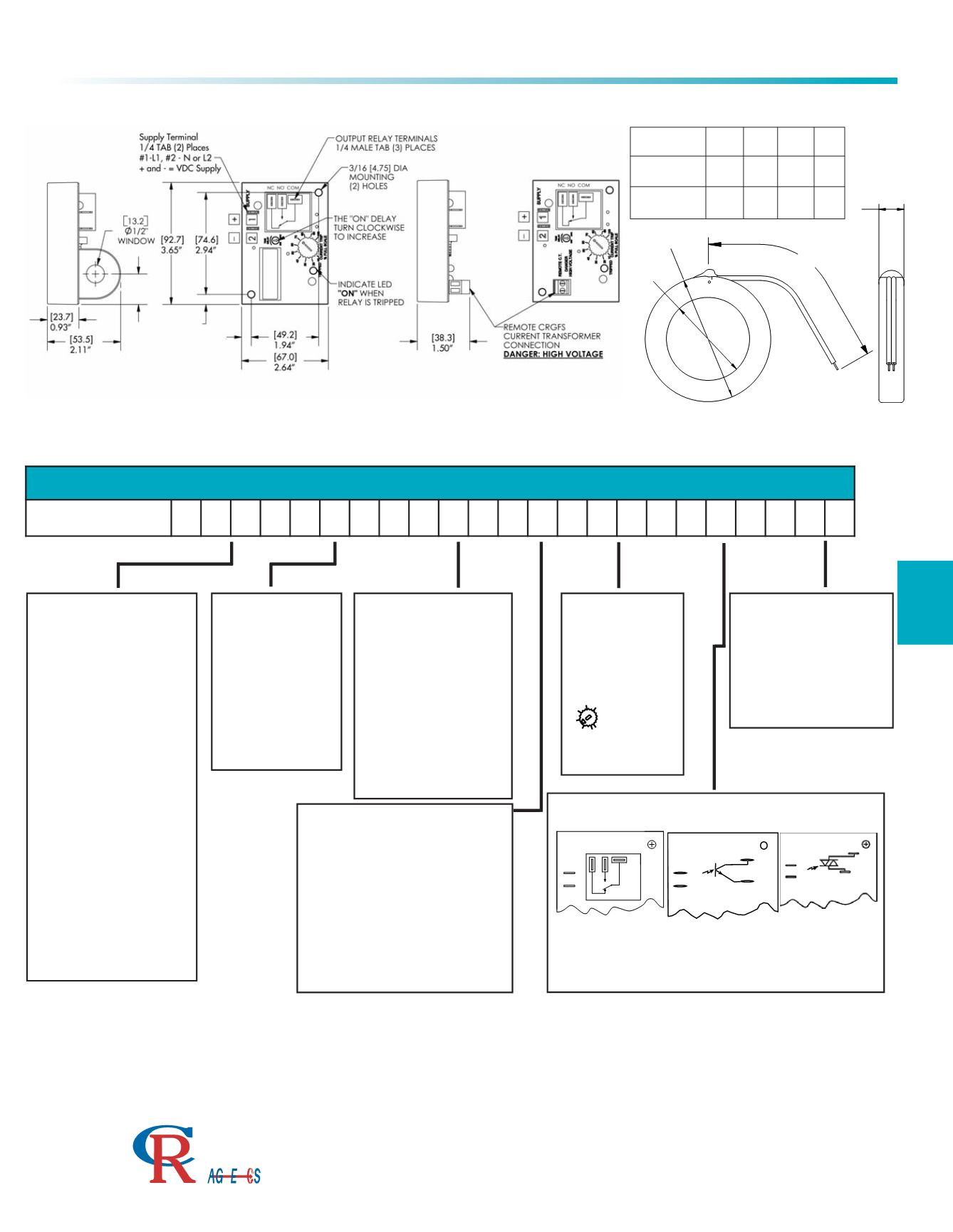
OUTLINE DRAWING
TRIP STATUS
EH
- Energized on High, trips
when sense current is above trip
point and returns to non-trip
status when sense current is
below the trip point.
EL
- Energized on Low, trips
when sense current is below trip
point and returns to non-trip
status when sense current is
above the trip point.
LH
- Latch on High, trips when
sense current is above trip point
and remains tripped until
supply power is removed.
LL
- Latch on Low, trips when
sense current is below trip point
and remains tripped until supply
power is removed.
SUPPLY VOLTAGE
AC
120
- 120 VAC
240
- 240 VAC
DC
24D
- 24 VDC
All supply voltage tolerances
are ± 10 %
TRIP RANGE
110
- 1.0 to 10 AAC
330
- 3.0 to 30 AAC
660
- 6.0 to 60 AAC
101
- 10 to 100 AAC
The trip ranges shown are for
one wire pass through the
window opening. The trip range
may be proportionally lowered
with additional wire passes
through the window.
TRIP POINT DIAL
CD
- Calibrated Dial
FP
- Fixed Trip Point
(Specify value of fixed
trip point with order)
I
- INTERNAL TRANSFORMER
R1
- REMOTE TRANSFORMER
w/ CRGFS-100
(1.60” window diameter)
R2
- REMOTE TRANSFORMER
w/ CRGFS-200
(1.75” window diameter)
3
5
10
15
30
20
CURRENTTRIP
D
25
No adjustment
dial provided with
the fixed set
point option
- CD - FP
-3.30 trip range shown
OUTPUT OPTIONS
ELR
Electromechanical
Relay
NPN
Optoisolated
NPN Transistor
TRC
Optoisolated
Triac, Zero Crossing
NC NO COM
-
+
+
D
63
Current Sensing Relay
CR4395 Series
3500 Scarlet Oak Blvd. St. Louis MO USA 63122 V: 636-343-8518 F: 636-343-5119
Web:
http://www.crmagnetics.comE-mail:
sales@crmagnetics.comThe Professional
Energy Monitoring
Company
ISO9001:2008QualityManagementSystem
M N TI
Top view of Current Sensing Relay
Shown with Remote Current
Transformer Option (-R)
A
B
C
D
Remote Current Transformers CRGFS - Series
CRGFS
A B C D
-100
2.88
73.16
1.60
40.58
12
304.8
0.79
20.07
-200
3.25
82.55
1.75
44.45
12
304.8
0.82
20.83
TRIP ON DELAY
A
- .5 to 6 Sec.
B
- 2 to 25 Sec.
C
- .1 to 1 Sec.
X
- none
Time-on delay is the time from when the relay trips to
when the output energizes. The ranges are
guaranteed minimum, actual range may be slightly
greater.
PART NUMBER
CR4395
-
-
-
-
-
-
-
Relays, Switches, & Sensors
Example Part Numbers:
CR4395-EH-120-110-CD-ELR-I (Relay with CT on board)
CR4395-EL-240-330-CD-NPN-R1 (Relay with external CRGFS-100)